Showing posts with label DCC. Show all posts

Monday, 12 July 2010

Better Late Than Never

Wow! That was good wasn't it? Expo, I mean. 50 years? It seemed like there were nearly fifty layouts.

Well done to everyone who contributed in whatever way.

Now I know, I haven't blogged for what appears like fifty years. But so much gets in the way of modelling sometimes. Suitably encouraged by Expo, where Brafferton performed reasonably well for much of the time, I press on.

For Oxford, I painted two part backscenes to relieve the mass of hardboard that would have otherwise formed the backdrop. On my return, I've started using these to sketch out what the backscene really ought to look like:


Also, the 04 finally got chipped and seems to be running well in it's new DCC state.

The legs on Brafferton were commented on quite a lot over that Expo weekend. These were substantially the idea of Edward who also helped with their construction. Indeed Edward and Alan Smith have contributed greatly to the legs and baseboard side of things on Brafferton; thanks for your support guys:


How long to the next blog? Soon, soon...

Tuesday, 19 May 2009

Posing the 04

As well as model railways, one of my other keen interests is photography. However, I've never really mastered the art of taking good model shots. Maybe I'm in too much of a rush, maybe I don't get the lighting just right... most of the pictures I take for this blog are purely for the purpose of recording progress (or lack thereof) rather than as a picture in its own right.

Having nearly finished the 04 (wheels back from Gordon at the end of last week), I thought I'd try and take some more worthy snaps; here are my initial attempts. The first thing that struck me is how obvious some of the original colours are showing through on roof edges, grab handles and coupling rods. To be fair these are substantially less apparent on the actual model (thank goodness!). I'm quite pleased with the actual photos; I think my technique is improving. These images posted here are about 25% of the resolution of the original shots; imagine how scary they look!


The model now awaits DCC chipping; I think I'll get one of the Zimo chips which should be small enough to go in the cab area.

Thursday, 30 April 2009

Brafferton Update 22: Adventures in DCC Pt 2

A spiffing time was had at York show over the Easter holidays; operating Edward's layout "Niddbeck Bridge", looking at the various other excellent layouts and spending a bob or two.

Following my last post, I got some very useful feedback from those members who actually know what they're talking about in DCC. As a result the DMU was reprogrammed with one address for both chips and the lighting problem fixed quite painlessly. However, I was made aware how convoluted it can be programming a chip via a handset; the limited number of buttons on the LH90 for example make changing anything quite a chore. So with a little good homour intact, I dug deep and bought a Sprog whilst at York.

These wee beasties ain't cheap and they take some setting up (put the CD ROM in your computer which then tells you to download the software from the internet; what's all that about then?); however once up and running it was a revelation! Stick the chipped loco on the track and use the computer program to "read" all the settings; the program can even assess the kind of chip used. Store these on your PC. Change any setting; address, reverse mode, motor profile. All a simple and obvious click on the PC. There are some nice pages with graphs for acceleration profiles. I've not tried these yet, but as I become more proficient, I can see they will be useful. So all in all money well spent.

Monday, 30 March 2009

Brafferton Update 20: Adventures in DCC

Having successfully forced my way into the Farish DMU yesterday and installed a Lenz Silver, I today set my mind to programming. A second chip was inserted in the trailer unit; this seems a rather expensive option just to control the lights. However it seems to be the most straightforward so I'll just gulp and accept it.

The chips were then given consecutive address numbers; 0405 for the power unit and 0406 for the trailer. I must be getting good as I then worked out how to join them in a multiple unit. It went a bit downhill after that; the two ends display the same colour lights at the same time! The power car is correct, but the trailer is wrong. I'll need to work out what to do next; presumably altering the direction CV will correct it. Unfortunately, at that point the kids arrived home from school and any pretence at concentrating was lost!

A job for an evening perhaps. For now, though, here is the Liverpool service coming toward you:

Sunday, 29 March 2009

Brafferton Update 19: Point Control Pt II

Onward, onward!

Having prepared the Tortoise machines and the baseboards as mentioned last time, I proceed to fit the two together. This proves fairly straightforward although the template provided with the motors was of no use; I found I had to position an actual motor and hold it whilst making sure the throw either way was sufficient. I then marked its position before drilling and screwing. 

Four in on board No2, two more on this board and a further two on board No3 (which still awaits track):


The motor control will not, I have decided, be DCC. Instead a small panel will be mounted on the baseboard to control the points mimicking the lever-frame on the prototype.

Although curved boards are excellent for forming a circular layout (how else would you do it?!), the boards individually can be a bit awkward. Edward Sissling kindly manufactured two "ends" to be affixed to a single board whilst work is underway. This makes them more stable and also protects trackwork and board edges from "knocks":


I also today chipped my Cl108 DMU. All fairly easy apart from the initial removal of the power unit body; it seemed to be tack-glued to the motor unit.

Anyway, more progress tomorrow. I hope!

Thursday, 20 November 2008

'Peak' Decoder Installtion & Running-In

My 'Peak' now has a decoder chip fitted, in the shape of a Lenz Silver Mini (with cable harness). Whilst I appreciate the super-slow running that can be achieved with the likes of Zimo and CTE decoders, as so amply demonstrated by Nigel C and Nick M at the AGM, I find that Lenz Mini decoders serve me well. As impressive as it is for a loco to creep along at a yard every 5 minutes it's not usually something that we need to replicate on our layouts. In the real world time is money and most train operations at done as quickly as possible, even shunting operations. So all I need from a decoder are smooth stops and starts and a respectable but not super-slow speed at 'throttle notch 1'. Certainly having the majority of my fleet on one familiar decoder type helps when it comes to decoder tweaking. I do have a few examples of CTE decoders in stock and one will be going in my 04 shunter very soon, purely on size grounds.

The picture below shows the general arrangement. The decoder sits in the milled recess, tucked on top of a slip of black fag paper for insulation purposes. I'll probably replace this with PVC insulation tape before final reassembly.

In the next shot you can see the orange wire connecting to the now isolatied motor, routed via the milled slots.

Here you can see the red and black pick-up wires connected to the two halves of the chassis block. The chassis block is drilled and tapped 12BA and a couple of terminal tags made from scrap etched nickel silver.


In the final shot we see the loco with body back on, undergoing testing and running in on a Bachrus rolling road. The cosmetic bogie outer frames have been left off so the wheels and gears can be easily observed. These are great if you don't possess a circular test-track or layout but don't rely on them 100%. At first the loco ran well on the rolling road but on the track had an intermittant and very annoying 'stall' whilst running on the first three throttle notches. I eventually stripped the bogies back down again and found a few tiny rags of plastic swarf on the rear faces of the wheels near the axles, left over from the wheel turning process. These were removed with a scalpel and the bogies reassembled, also paying attention to pick-up strip adjustment. Running is now good and it runs very slowly at throttle notch 1 without a stutter now.


The only other problen I identified was that the outer pony wheels had insufficient side play on 24" radius curves, so I removed the previously installed limiting spacers. The pony wheels now actually just kiss the inside of the narrowed cosmetic side frames on 24" curves but not enough to stop them revolving or derailing.

Wednesday, 19 November 2008

A Virtual Loco For DCC

Here's an interesting and useful bit of kit for the DCC'er who fits a lot of decoder chips - the ESU decoder tester. I have in the past had a couple of chips that were faulty from new but didn't find this out until after the wires were cut and several hours were spent installing them. The tester acts as a virtual loco and has a can motor with brass flywheel, a speaker for sound chips and interfaces for all current decoder types (6, 8 & 21 pin and loose cable). You can quickly plug-in or hook-up a new decoder, connect to your DCC system and check it out. It can also be used for adressing and programming decoders before installation, but only to a certain extent. Also if you have a DCC loco that suddenly stops working the tester can be used to quickly 'prove' the decoder and save time messing about with the actual loco with suspected pick-up faults etc.

In the picture below you can see a Lenz Silver Mini Direct decoder plugged in at the left hand side. I have two of these in my new Farish Derby 108 DMU (one for each car).


In the next shot you can see a Lenz Silver Mini with cable harness hooked up to the sprung terminals. This will be going in my class 45 'Peak' diesel conversion. The tester is connected to the 'PQ' programming track output on the DCC command station and the decoder is being 'read'. The handset is displaying '0003' which is the factory set default address for all DCC loco decoders, so all is well. Programming track outputs are at very low current so no damage can be done if you've fluffed your installation. The motor should 'pulse' three times for a few revolutions as it is being read. If you get an 'ERR' error message you have probably got a duff chip, but check your connections are good first!


The tester can then be connected up to the main track outputs from the command station and the decoder can be played with. The tester has tiny LED's that can prove that 'F0' lighting functions/directions are working correctly. Other functions such as the 'F3' half speed-range shunting mode setting are also tested. I consider it £29.50 well spent. Any DCC retailer worth his salt should have one of these and use it to test decoders before despatch!

Saturday, 15 November 2008

DG's On 45

Work continues on my Farish 'Peak' conversion, with DG couplings now fitted.

The bogie frame assembly is a U-channel plastic affair. This shot shows the end filled in with a double thickness of black plasticard, drilled 1.1mm, tapping size for 12BA. It is secured with 2-part epoxy.


In the shot below we can see the rear of the plasticard infill, with a captive 12BA nut. The plasticard is counter-bored undersize and the nut pressed home in a vice, before the infill is bonded in position.


Below we see the cosmetic outer frame/bufferbeam unit clipped back into place. The original Rapido type coupling slot has been widened to about 2.25mm and lengthened by about 1mm.

The DG coupling was drilled 12BA clearance size and then bent through 90 degrees at the point where it widens out to it's mounting plate. The bend position is first scribed with a scrawker, to ensure a neat, tight bend. After bending it is reinforced with solder.


Here we see the underside. A 12BA screw with head diameter and thickness reduced and reslotted with a one of those ultra thin 0.3mm files from shop 1.


The couplings and screws have now been blackened and buffers reinstalled. The saw cuts need filling/tidying and the red paint touching up. How many of the brake pipes etc can be installed without fouling the DG couplings remains to me seen!

Over the weekend I will be fitting the decoder chip and reassembling the loco. This loco is going to be renumbered as D32 which as far as I can tell was the only Leeds Holbeck based machine with centre headcodes prior to March 1965. It would be great if Farish could do a split headcode version!

Thursday, 6 November 2008

I Dream of Wires

Another small step forward in the race to have "Brafferton" something like for Expo 50. As I am going down the DCC route, the layout will be wired accordingly. To be honest, I can't see that there will be that much difference from an analogue set-up other than the ommission of isolation switches. And I might still put some of those in yet, for de-bugging purposes.

So, on board 1, we have a very technical arrangement; two rails, two busses and three connections! You will see that I did manage to position some copperclad sleepers over a baseboard truss, hence the wire runs at an angle from the trackbed to the main board:


Here you may marvel at the complexity of it all! On the next board the busses will need to be offset to avoid the various point mechanisms etc. but here they can just follow the approximate line of the track. Short term there are flying crocodile leads to allow power to be connnected:


Saturday, 25 October 2008

Chips With Everything

With 'Niddbeck Bridge' not due out again until York next Easter  I'm taking a few weeks off from layout detailing and concentrating on locomotives, namely my Farish Drewry 0-6-0' shunter and my Derby type 4 1-Co-Co-1 'Peak'.

The class 44/45/46 'Peak' was first all-new Chinese made  Farish diesel, but  is not to the latest 'DCC Ready' standard of the 37's, 57's and 42 'Warships'. This means the chassis block halves need modifying to isolate the motor, house the decoder chip and route the decoder wires. This can be done using burrs in a minidrill and hand tools but I opted to do it the quick way in my Proxxon MF-70 mini milling machine. Farish chassis blocks are soft mazak zinc alloy castings and really quick and easy to machine.

The picture below show a chassis block half after machining. The top section has been milled out to house the decoder, a wiring route has been milled along, down and then across, and the area where the motor brush tag previously contacted the casting has been machined away.


The picture below better shows the smaller square area that has been milled away to clear the motor brush contact points.

These bare machined areas have subsequently been touched up with black paint to provide a degree of electrical insulation.

In my next post I'll show you the bogie modifications I'm making before reassembling the model.

Tuesday, 15 January 2008

Through the Wires

As promised, here are some pics of the N8 showing the chip installation.

i. General arrangement. The wires have been tweaked a bit more now, so that the front of the chip is higher.


ii. Front view showing the various bits of wiring. There is very little room either side of the motor and none on top where the rear spectacle plate actually touches the top of the motor. In comparison to find space for the wires, getting space for the chip was relatively easy.


iii. As such the wires are visible along the inside of the footplate; being orange doesn't help either! A touch of dark grey should render these much less obtrusive; the light grey one on the other side is less obvious even in its original state.


iv. The chip nestles nicely in the roof space and from all but the lowest viewpoints is invisible. A relative success and fairly quick and easy.


Sunday, 13 January 2008

Lets Get Digital

As I mentioned in the VAG, my Lenz system is now up and running. I have also successfully chipped the N8.

I thought the chip would fit in the tank area, but it soon became apparent that I would need to remove some of the boiler, and associated weight, to get sufficient space above the wheels. The cab area was the backup and I initially decided that I could stick it to the motor with some of the double sticky foam that comes with the chip. This proved to be too obtrusive; the chip and foam were very visible astride the motor.

By then, I'd wired the chip in as per instructions and it became apparent that the wires were sufficiently stiff to carry the chip. I therefore removed the foam and allowed the chip to float free. By tweaking the wires, the chip sits snugly inside the roof area and is substantially less visible. As recommended, I insulated the inside of the body against potential shorts; sellotape worked fine for this.


If I were building the N8 now, I'd allow space to mount the chip in the tanks. The result I have is the best, I think for a loco not built with DCC in mind. Here, with the help of my daughter, are my first tentative steps into DCC;


I'll post some close-ups of the loco in the next day or so.

Wednesday, 19 December 2007

False Start

So that's the NE Xmas bash over for another year. Very nice too; lots of lovely grub and one of Micks private DVDs to boot.

Well a privately owned DVD about colliery lines in the North-East anyway. An excellent DVD with cinefilm from the fifties through the early seventies and bags of atmosphere.

There was a good selection of models on show from various members, and I took the D49 and got some valuable advice from Bob as well as a spare bit of etch which I'd pinged the original of.

Now I mentioned that I was going DCC and recently took delivery of a Lenz 90 Set, Transformer and 2 Mini Silver Decoders. Unfortunately on powering up, the handset didn't respond, merely shining all of its merry LEDs at me! I rang the supplier who offered a replacement, but suggested I speak to Mackay Models before doing so as they might have a simple solution. They didn't, but offered to sort the problem for me. Very decent seeing as they didn't sell me the kit in the first place! I await the returned, working, items with eagerness. No doubt it will be after Christmas now...

Thursday, 6 December 2007

Close To The Edge

Well, we're really starting to chart unknown territory now.


The next step is to fabricate and insert the "Piston" tubes into the cylinder block. This is fairly straightforward; carefully shortening the tube in the mini-drill and regularly checking length. Then soldering into the cylinder block flush with the front and protruding somewhat at the back. I used my small soldering iron (an Antex 12W) for the first time in quite a while. I've got used to using the 18W; the extra power more than compensates for the bigger tip. But here there isn't the space and the 12W works just fine.


Slidebars come in three pieces and the instructions say to tack solder them at the front only. I presume this is to avoid solder in the slide slot which may impede the smooth flow of the Crosshead. The Slidebar is at the bottom of the picture:


The scary bits are at the top of the picture; the Crossheads. Now I know the instructions say to read the instructions etc. etc... But by the time I've got to page 6, I've forgotten most of page 5, and so on... So despite the instructions, I removed the pieces from the etch. Mainly because they seemed to be flopping around when I'd removed some other pieces, not out of any perversity you understand. Some very flimsy rings have to be reamed out to slide over the 0.7mm rod and then folded over on half etched hinges to make three layers. I managed to break two lots of hinges whilst reaming, but subsequently the whole lot did get soldered onto the rod.


Having done this, another piece has to be soldered on square and with the minimum of solder so as not to obscure some tiny holes. Here I failed; the pieces are square, but the holes are full of solder! Nevermind; I shall drill them out. Anyway the Crossheads do slide nicely in the Slidebars. The instructions tell me not to fit all this to the chassis yet as there is more work to be done. Oh crikey!!

Seriously though, this is some of the hardest fabrication I have had to do. It has required constant concentration and effort, but the results are more than worth it. Bear in mind the whole assembly is smaller than your thumbnail (unless you have particularly dainty hands).

The Crosshead sticking through the cylinder block. Not as painful as it sounds.

The Crosshead in the Slidebar; all slippy and super smooth. Don't sneeze though...

The other thing to mention is that this will be my first DCC loco; I've decided to take the plunge! Fingers crossed!!!!

Tuesday, 20 November 2007

Still Here

Still here, still doing a bit, but not as much as I would like. Eight months into our new house and still jobs to do each weekend. Freddie the labradoodle is also now eight months old, getting bigger and needing much more exercise each day...

The station building for 'Niddbeck Bridge' is now ready for painting and then window fitting. The Scalelink chimbley pots look good, even if their online store charged me nearly £5 p&p and sent them in a small jiffy bag with 48p worth of stamps on it...

The plan is to paint all the stonework on the layout in one hit, so have just finished the concave platform and am now working on the horse/cattle dock. These use a lamination of 2 x 5mm foam core board, then spilt down to about 7mm using a wide CK scraper blade. The edges are clad in stone plasticard, stepped out at the top so as the be a close approximation to the published NER standard design. The platform edgings are scribed plasticard at a scale 4'x3', also NER standard. These were precast concrete with a cross-hatched or dimpled anti-slip surface which I did try to press in using a vice with serrated jaws, but could not get an even result. I doubt it would be noticed under a coat of paint any way!

If I can prise the camera away from the wife and No.1 son I might take some pictures to post up this weekend.

Latest DCC purchase is a natty ESU decoder tester with integral motor and speaker. This means I can now test decoders straight out of the box and before any fitting work or lead-wire shortening. I have had a duff decoder as delivered and it's annoying to spend a couple of hours fitting them only to find they don't work.

Tuesday, 3 July 2007

Plodding On


Work done over the last 10 days has included making a start on the civil engineering side of things; namely a tunnel mouth and a girder road over bridge. These form the scenic breaks at either end of the station. Construction is Slaters Plasticard 2mm dressed stone, chosen after a pointer from the VAG (thanks Paul).

The road bridge is modelled from a photograph of the one at Ripley Valley station on the Pateley Bridge branch, the location that inspired the layout. The tunnel mouth is freelance, but retaining the same style as the bridge. These structures will be finished off and installed once the curved backscene has been glued into place.

The backscene is currently on the workbench and is 150mm high foamcore board. I am using 2 thicknesses of 5mm and am making it bendy by lots of vertical knife cuts, approx. 4mm deep, at 5mm or 10mm centres according to radius required. The two thicknesses are then curved and the 'cut' faces bonded together with PVA, thus holding it all to shape.

On Sunday I sprayed the scenic area track in a gungy dark brown track colour made up from 3 Humbrol and Railmatch enamels and let down with cellulose thinners. I applied this using my Aztec double action airbrush, the first chance I have had to use it since buying it over a year ago. It was a review in MRJ a while back that prompted me to buy one and I'm quite impressed. Looks cheap and cheerful being 98% plastic, but it works a treat, does not seem prone to blockage and cleans up after use very easily.
.
The track will be ballasted (to represent typical NER branchline ash ballast) once the platform edges, bridges etc are installed. The rail and chairs will then be brush painted in a rusty shade etc.
.
Edward S

Friday, 15 June 2007

Big Knob or Little Buttons?


Other work completed on 'Niddbeck Bridge' this week has seen final hooking-up of the'XpressNet' around the layout. This allows you to roam with a handheld throttle and plug-in where ever an outlet facia is located. I have 2 on the rear and one on the front.

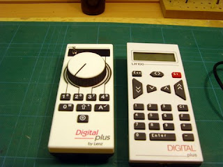
Each LA152 facia panel has 3 outlet sockets (2 x DIN type, 1 x phone type). This has allowed me to have both my Lenz handsets working concurrently for the first time. The handset on the left is an LH90 with knob control and LED display and the righthand one is a LH100 with full keypad and LCD display.

Why would I want two handsets you might ask? Both have their good points and bad points and my opinion is that ownership of both is a good idea. The LH100 with its full keypad and better display is great for decoder programming and setting up things generally. On the downside I find the button speed controls not as easy to use as a rotary knob and it only has a loco memory stack of 2 addresses.

The LH90 is an ideal driving and operating throttle but less easy to program with due to the lack of a full keypad. With the large rotary knob and traditional toggle reversing switch I find it easier to drive trains without having to look at the throttle, something I find I often have to do with the LH100. The LH90 also has a loco memory stack of 8 addresses which is much better. When in accessory switching mode, the '2' & '3' buttons allow you to scroll up and down the accessory list adresses (ie points, signals and uncouplers) and the '1' and '4' buttons act as the -/+ switches. Whilst in accessory switching mode the last loco called up remains under full control of the knob and toggle switch, so is an ideal arrangement for shunting.

Another option is to use the LH90 as my loco cab and the LH100 as my signal box. Great fun this DCC business!

Another afterthought has been the addition of a isolated 200mm length of programming track on the fiddle yard, as I thought this might be useful at exhibitions. Prog tracks allow decoder installations to be 'read' and tested at lower power and will avoid a blown decoder if an incorrectly wired or badly insulated loco is subject to full DCC power. It is also safer the change decoder CV settings on an isolated programming track. It can be done 'on the main' but you risk changing settings on other locos if you make a mistake!

Apart from a layout stand and a lighting rig I must now turn my attention to architectural and scenic development of the layout, or proper modelling as no doubt many of you will think!

Edward

Thursday, 14 June 2007

Well Stacked...

No, not todays page 3 'stunna' , but my recently constructed DCC power supply and command 'unit'.

I claim no credit for the idea, having copied something similar that Chris Dening (son of Jon Dening, well known ex-Association member, now into 7mm) uses on his Canadian HO exhibition layout.

The idea is to keep all the power supply gubbins, command station and booster (if used) in one floor standing unit and then to feed up to the layout using an 'umbilical cord' on just one plug rather than several. Keeps things neat and tidy, aids storage and transport and speeds up exhibition set-up and break-down times. Or thats the theory anyway!

Construction is quite straightforward; some varnished 9mm birch-faced ply, a length of 1/2" aluminium angle, some 1.5mm ali sheet (cut up from a door finger plate), a couple of 4" aluminium cupboard D-handles and four little rubber feet. Most these items should be obtainable from your local DIY emporium. On the electrical side there are a couple of red indicator lamps and a 25-way D-socket, purchased from Squires.


The two power supply packs (the smaller Lenz TR100 45VA unit which supplies power to the LS150 accessory decoder and the larger Lenz TR150 70VA unit which supplies the LZV100 command station) are the heaviest lumps and these go side by side at the bottom. Above it goes the LZV100 command station (the brains of the DCC system). There is room to add an LV102 booster unit should I ever build a really big layout, or God forbid, move up to the big 7mm+ scales !

The two indicator lamps are wired to the output side of the power packs to give an at-a-glance indication that they are working....beats trying to listen for the gentle hum in a noisy exhibition hall!

Obviously this unit can transfer from layout to layout so should prove to have been time well spent this past week or so.

Edward S

Thursday, 7 June 2007

Fence Houses Insulated Re-Railer Ramp


As promised here is a pic of the DCC-friendly (and DC too) insulated etched re-railer ramp from Fence House Model Foundry.

Plasticard is used to space the two halves apart, and the etched tabs are then snipped out after the epoxy has set. The wedge shaped top guide piece is also plasticard, marked out using the supplied etched template.

The grove that has been filed into the top wheel guide is to clear the iron droppers on DG couplings.
Edward S

Wednesday, 30 May 2007

Back In Business !

Just to advise that my new home workshop is now just about complete (needs a roll-end of vinyl flooring to finish off) , all my modelling gear has come out of storage and has been dusted off.

Work on 'Niddbeck Bridge' will recommence just as soon as the June 2mm Magazine has been stuffed and posted. I aim to post up progress reports and pics here at least once every week.

The embryionic layout performed well at the NE 'Bash' earlier this month. The only problem that came to light was a dead point vee in the fiddle yard. I need to check if this is a dropper feed wire problem or an issue with the 'Hare' decoder that does the switching.

The 'XpressNet' circuit on the layout needs finishing off and and the cable harness that will link the command station and transformers (free floor standing) and the layout needs making up. I am using 25-way 'D' connectors for this task.

A full day of operation at Bournmoor brought home to me one of the short-comings of DCC - that inadvertant short circuits trip the whole system out until cleared. This is most easily caused by driving a train into a trailing point that is set against it! Fortunately the 'Hare' decoders I use with the 'Tortoise' point actuators have a built-in 'Auto-Throw' feature, so I will need to set this up. It just needs 50mm sections of rail behind the point to be isolated and wired into one of the terminals on the 'Hare'. If a train then approaches a point that is not set for it, the point will immediately be thrown and a short circuit avoided.

This DCC 'short circuit' business also led me to ask Bob Jones to design me an insulated version of his Fence Houses etched re-railer ramp. This he has done and a 'split down the middle' test etch was put together over the weekend. The two halves are simply epoxied together using plasticard spacer on the underside and the etched spacing tags are cut away when set. Photo to follow.

Edward S