Showing posts with label D49. Show all posts

Thursday, 3 July 2008

Get on with some modelling, Simms!

Enough of all this prattle about looking at other peoples layouts and spending money! I have actually done a (very) small amount of modelling in the last week or so...


The D49 approaches the finish line albeit rather slowly. While I've been sticking small details onto the loco body, the chassis has been running in. Here you can see the addition of; cab side steps, buffers, steam pipes from the boiler to the cylinders, smokebox door, chimney and dome. There are still a fair number of items to go; front steps, grab handles, whistle, valves, Wakefield lubricators, not to mention the cab roof. I also need to fabricate a backhead to go in the cab.


The more eagle eyed of you will have noticed that the loco was stood on a piece of Easitrac. I assembled four lengths in less than 1/2 hour and even glued one down! You can see from the unglued sections that there is severe wobble on the rail. Gluing the track down overcame this issue, but I hope that the tension won't subsequently lift the track unit! Onward...

Wednesday, 11 June 2008

Ain't no use in crying

Oh well, there go the last two months. No modelling done whatsoever. Sometimes these things happen; the business needed some attention (in a positive way; new staff, new flooring, new equipment, new products/services), there were family matters including a week's holiday and to cap it all, the missus decides we need to move house! So the railways go on the back burner...

Anyway, I hope that this week's return to service will be sustained and I can make some layout headway. Today I've tried to get the D49 a bit nearer the finishing post:


Handrails manufactured from .3mm nickel silver wire and fitted using my normal process; 36swg phosphor bronze wire twisted in a collet around a bit of spare .3mm wire.


On this side we also have the reversing mechanism (below the handrail and above the splasher). This shaft driven mechanism is I believe peculiar to the D49/2s and whilst the parts are listed in the instructions, there is only mention of steam reverser and lever reversers. I used one of the three layers as the intermediate support as the gearbox seemed adequately represented by two layers of etching.


The last job this afternoon has been to add more weight in the form of liquid lead; in the boiler space between the driving wheels and also in the boxes above the rear drivers. Hopefully the glue will be solid this evening and I can have another wee dabble...

Tuesday, 11 March 2008

For The Signal Is At Green

And following on from that short interlude, here at BBC 2(mm) we return to our scheduled programme of botching and struggling that is "How (not) to build a D49".

Well actually, and touch a very woody piece of wood, things seem to be back on track. The signal is up (or down, or green depending upon your prototype) and I think the end is in sight!

First up, the smokebox saddle was bent up and soldered onto the footplate. Then I set to manufacturing the boiler. Bob provides a lovely template to glue onto your brass tube which gives all the necessary positions and cuts, providing of course you glue it on square. I did my best to get it so, but whilst square, there was a little bit of overlap where the two edges met underneath the boiler. Was the template slightly too large or is this intentional? Using the handrail holes, which should be just above the centre line, as a guide, I'd say the template is accurate. As you can see, this loco will be finished in the rather rare "paper and inkjet" livery; locos tended only to carry this in the early months of their lives. At the moment, the boiler is located solely by the screw inside the cab.


The toughest part of the manufacture is shaping the firebox. Making the cuts with the piercing saw is not a problem. Opening up the flaps and getting them to the right shape is a bit more tricky. There is an etched insert to use as a guide, but this took quite a lot of fiddling to get right. Here we see the insert and associated nut soldered inside the shaped boiler.


Another important point is to get the rear of the firebox dead square; otherwise when the screw is tightened, the boiler will stick off at an angle, to one side or the other, or up into the air! A similar problem will arise if the nut is not square to the firebox back.


It's all getting a bit exciting now! The boiler is on the body which in turn is on the chassis, and the character of the loco is starting to become evident. At this point I'm also making sure that there is adequate clearance between the wheels/flanges and the firebox sides. In this shot more metal needs to come off.


Don't forget that if you miss any instalments of this exciting series, you can now catch up at BBC iPlayer. Alternatively just scroll the page down...

Sunday, 2 March 2008

Stoke Up Fireman

A somewhat frustrating week, modelling-wise, with little progress to report. Here is a quick catch up on the work that did get done in the earlier part of the week...


Was it the frustration of the problems reported last time which slowed things down? Perhaps. Here we see the twiddled front end; I think the upper frames are slightly better seated now.


The cab overlays were also affixed along with the handrails. As with the tender, these handrails are etched and despite my initial misgivings about this idea, I think they've come out rather nice. I also enjoyed sweating the overlays on. Some care was required here to align the structural side with the half etched overlay. The handrail holes helped this process and I'm quite happy with the end result; it's starting to look like a loco now!

Because we have a kit designed solely for 2mm scale, the cab interior parts can be used with no fuss or bother; in 4mm shoot-downs you tend to find clearances are zero and it all gets a bit fiddly to make it work. Some backhead detail would be nice; I'll probably fabricate something from plasticard/brass once I've finished the kit.

Lets hope next week proves more fruitful than last...

Tuesday, 26 February 2008

Passengers Waving (Sinking not Waving)

Couldn't you just scream sometimes? Everything seems to be going to plan then a small error blows up in your face. With hindsight it all seems so obvious, but then if I had prior hindsight...

First up, we are fabricating the curved bits of footplate, front and rear and then inserting them along with the representation of the frames at the front:


Simple enough, no? No. My first error had been in the placement of the valances (see earlier post). These were too far back. Only slightly, granted, and mostly due to the relation between them and the front buffer beam. Also there are no tab/slots to guide placement. I should have been alerted when the front lamp irons were slightly skewed backwards when the front curved footplate was fitted. As a result, the rear curve sat behind the main footplate and not under it.

The cab was folded up and a trail insertion made. I expected this to be tight, but it was nigh on impossible to insert the footsteps through the slots and then get the cab to sit down flat; the curve on the cab repeatedly fouled the bend in the footplate.


The result was that I had to unsolder the valances and squeeze them forward a smidgen (all good technical terms, I know!) before reseating the rear curved footplate. All a bit hair-raising and the end result is not quite the perfection one would aim for, but now that the cab overlays are in place (photos to follow) the outcome is more than acceptable. Meantime here are the bare bones pictures. The gap evident here seems ghastly; it is less so now the cab overlays are done. Honest!

Tomorrow, I'll botch the rest of the loco body (or try to avoid doing so!)

Sunday, 24 February 2008

There and Back Again

A tad delayed, here is the update on the D49.

We are now on the final part of the build; construct the loco body. First up is the footplate. The basis of this is a fold up etch over which we are going to layer different etches to produce the finished item. We bend this to its basic shape including bending up the splasher sides. A full thickness overlay is then tacked onto this to represent the raised part of the footplate.


There are two valances to be attached to the underside of the footplate; these fit into some half etched grooves. We are instructed to clean all cusping off the etches prior to assembly; this proves rather tricky on a delicate piece like the valance. I clean the top flat which will fit into the groove and then do the rest when I've soldered it in place.

Once the valances are tack soldered in place, the footplate starts to look more convincing. The square bit protruding from behind the rear curve will apparently be filed away fairly soon. Next up, we need to add the curved bits of the footplate (after we've curved them of course!); should be good for some fraught nerves...

Friday, 22 February 2008

Time Flys By...

Doesn't it just? Where are all the posts then?

My excuse? Well we did have a weeks holiday in Wales, and the usual preparation beforehand and sorting out on return meant I lost about a fortnight of modelling in all. But we had a ride on the Festiniog and bought an Ivor the Engine book, so not all was lost! This in turn prompted me to buy the Ivor DVD on return from said holiday and that in its own turn prompted me to buy the Trumptonshire DVD box set. So thats probably where the modelling time went. As they say, "Time Flys By..."


Back to the workbench and I need to get this D49 thingy cracked and then bang on with the layout. Through Edward, I am looking to get Alan Smith to make a "baseboard kit" for Brafferton to give a professional job. If I do it all myself, it's going to be rather rougharse; woodwork was never a strong point for me. Whilst I wait on that, better progess the D49 hadn't we?


Next job on the list was to insert the worm and complete the drive train. This was relatively straightforward; I'd done worms and stuff before. However the kit includes etches to manufacture the universal joints; a new idea to me. So these needed building up.


No, these aren't to deter 2mm vampires. They're the two halves of the ball part of the joint which are each made up of three layers of etch. The two halves are then soldered around some spring steel wire and the whole slots into the slotted tubes on the drive shafts.


What is not overly clear in the instructions is that these etches need a fair bit of meat taking off once assembled to enable them to work in the joint. Once one end had been done, I tacked half of the second assembly to the other end and check for length before fully soldering all parts together. My guestimate was quite good and I didn't need to shorten or lengthen the assembly after the trial run.


Once fully soldered, I gave the lot a right good clean and a dab of oil before checking the finished assembly for fit...


A quick wobble up and down the test track (no weight yet!) proved success. Now onto the loco body. I've done a bit this afternoon, and I'll try and post an update tonight or tomorrow. I'd hoped to get to Glasgow this weekend to see Mick and co at Model Rail Scotland. This is now looking unlikely due to work and family commitments. Shucks...


Friday, 1 February 2008

Don't tell him, Pike!

Stupid boy!

Yesterday I wrote "no mistakes" at which point Uncle Bob e-mailed me and pointed out the glaring error. The bearings for the pony truck go through the link, but ARE NOT SOLDERED so that when you tighten the retaining screw, you have a pivot. What a bufoon I am! Thank you Bob. Bearings have now been removed, the link cleaned of solder and new bearings merely PLACED in the holes.

On a brighter note, I've tweaked the brake assembly and this now sits in place without fouling any moving bits. Whether I get any farther tonight or tomorrow morning I don't know.

If you're coming to Bournmoor tomorrow afternoon, you can see it in the flesh (no, the D49 I mean!).

See you there

Wednesday, 30 January 2008

Saddle up the Palamino

More progress today:

i. Pony Truck. As per instructions. Straightforward, no mistakes (as yet discovered!)


ii. Brakes. Again fairly straightforward; fold up and solder with 0.3mm wires.


iii. Pony Truck on Chassis.


iv. Brakes have been on chassis, but I'm getting binding somewhere. A job for tonight or tomorrow night, perhaps!

Tuesday, 29 January 2008

Under Cover

Are you ever doing some modelling and you get to the point where you think, "Ooh, I never thought about that!"? Well I had just such a revelation at the start of the week.

The D49 chassis is up and running very nicely and all the motion is in place. It's at this stage that I notice the piston rods protruding from the front of the cylinder blocks. "When should they have come off?" I think. "It's going to be a bugger shortening them in situ!" Indeed it is...

I can't find any reference in the instructions as to when I should have shortened them and this makes me feel a little better. Ideally I would have done it before securing the crossheads and slidebars. As it is, I now have to cut them flush with the face of the cylinder without marking the said face too much. Tricky...


The piercing saw proves ideal, but work is slow and careful. Fortunately the piston covers will mask any markings on the cylinder front and the same cover is also half etched where the piston protrudes, so it doesn't have to be dead flush.


Meanwhile the bogie has been assembled and I hope to fit the wheels later tonight or tomorrow. Onward, ever onward...

On a green note, I replaced the bulb in my modelling anglepose lamp with one of these newfangled low energy ones. At 11W it obviously uses lots less electricity, but also the light seems somehow "cleaner" than a 60W standard bulb; I am finding it a lot easier to distinguish fine detail on my work. Additionally the heat thrown off is substantially less; certainly useful once we get into spring/summer.

Saturday, 26 January 2008

... Loco Motion

Motion: Part the Second.

On the right hand side of the D49/2 is the valve-gear; slightly different in that it has Lentz rotary poppet valves. A crank on the foremost driver rotates bevelled gears which drive through a shaft into the cylinder. Further gears and shafts operate the valves in the two cylinders.

Whilst relatively straightforward, the model set-up involves the mock gearbox "floating" on an etched arm and the drive shaft. The bracket, which in real life is attached to the footplate, serves no use in the model and the lining up of the components requires a fair degree of care.

There are no joints to manufacture on this side other than to solder the crank onto the crank-pin capturing the coupling and connecting rods and ensuring that the other end of the crank corresponds to the centre of the wheel. This was done by eye and I think is reasonably successful. If there is any slight misalignment, it is not obvious especially behind the gearbox.


The gearbox is manufactured from a fold up etch onto which we solder a small tube, to take the shaft, and a piece of 0.3mm wire to attach the arm that holds it. This seemed to be going swimmingly until I came to attach the whole to the chassis. On trimming the wires, I loosened the shaft tube; obviously the soldered joint was poor! Reattaching it, now that the gearbox was in-situ and the wires had all been trimmed, proved to be somewhat testing. Eventually I was happy that all was secure and in the correct place. Files and abrasives cleaned up the assembly before the whole chassis was given a thorough wash in the bathroom basin.


I consider the last few days work a success; despite all the gubbins which now adorns the chassis, it still runs very freely - better than I could have hoped for. I have learned some new techniques and pushed back my own modelling boundary a little further. Truth be told, despite the setbacks the motion has actually gone together much less painfully than I thought it would; I guess I can still surprise myself.


Now onto the bogie/pony (?) and then lets get some power to those wheels!

Friday, 25 January 2008

C'mon Baby, Do The...

Little discernable progress with the D49 over the last few weeks as the Layout Challenge kicks off. However I have been redoing the wheels; I was concerned that they were not sufficiently central when looking at the chassis face on. This became more apparent as I proceeded with the loco-motion. So out come the wheels and, similtaneously replacing the muffs, back in they go; hopefully this time more symetrically. This was a tricky process as the slidebars and crossheads are now in place and care is needed not to damage them.

Having undertaken this remedial work, I move onto the motion proper. You may recall that this is the work we are instructed to practice for. And it soon becomes obvious why. The links and arms are miniscule and making moving joints between them is a trial to say the least. This makes soldering coupling rod washers on seem a doddle.

The left hand side is the lubricating motion. At this point the instructions become quite dense and I found myself losing track and failing to understand how the whole was constructed. As well as rereading the instructions several times, I found reference to photographs in the RCTS book most useful and eventually felt confident enough to proceed. Manufacturing the two joints to assemble the three components was fairly straightforward; this work could be completed in the vice and cleaned up with relative ease.


Two close-ups of the motion in various positions. I'm not sure if the swing link should swing quite so much, but it doesn't seem to affect the running...


The assembly must then though be attached to the locomotive and necessitated holding the chassis in a cradle whilst the final joints were made. Attaching the swing link to the bracket on the chassis, the very last joint is the crank onto the the front wheel crank-pin. Being a layer of wheel > coupling rod > connecting rod > washer > crank, extra care was needed to avoid soldering the whole into a horrible mess. Once acheived, the whole lot was carefully cleaned up with files and abrasives and then washed to remove any stray flux.


A quick trundle up the test track reveals a working component; success albeit small in the scheme of things! Now for the other side...

Sunday, 30 December 2007

Moving Pictures

Tired of the Bond film on ITV, or the latest episode of Eastenders. Try my alternative below. I can see that Peter Jackson shaking in his boots...

The Wheels in the Frames

I hope that you've all had a Merry Christmas! Done any modelling? Sneaked away from the turkey and the jollities for a few hours? Well I managed to do a bit more on the D49 between the pudding and the Port. Fortunately before the Port!

Having fabricated the various bits of motion, I proceed to fit the gears and driving wheels. First, though, I remove the frame extensions; carefully parting them from the frames proper with my piercing saw. The ends are cleaned up with a fine file. Additionally the frames need to be coloured. For the first time on a locomotive, I thought I would use Gun Blue rather than painting. This has the advantage of giving good coverage without the thickness built up with paint. Both methods seem to rub slightly with use, but a light oil of the blueing seems to prevent this somewhat.


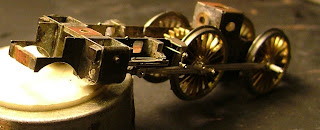
The fitting of the wheels was fairly straightforward and the drivers were soon in place and quartered; the coupling rods held in place with fine wire insulation. I then come to the motion; crossheads, slidebars and connecting rods.


The slidebar slots into square holes in the cylinder face and a small pip at its rear lines up with the hanger, further back on the frame, when it is sufficiently inserted. Some fettling of the slidebar is required to get it far enough in. I have not soldered the slidebar to the cylinder, but merely tacked it to the hanger, being careful not to solder the crosshead at the same time!


Similtaneously, the crosshead rod has been slid into the tubing in the cylinder and of course requires no soldering whatsoever.


One at a time, the connecting rods are placed over the front wheel's crankpin and smooth running is sought. This took a little time and some further fettling of the slidebars was necessary as they had a tendancy to distort slightly during fitting. The second set required a little more attention than the first, but eventually all is in place and running smooth.

Thursday, 20 December 2007

Cruel and Unusual

Now the next part of the instructions suggest you practice before proceeding. And quite right too. Following on from the Crosshead/Slidebar saga we are now going to make the various bits of motion. To be fair, the D49/2 is the easiest option as the valvegear is just .3mm wire and the various linkages and rocking bits are missed out. However I still need to solder some joints; initially the crosshead to the connecting rods.

The connecting rods are a simple double-up and sweat together etch. I was careful not to get solder near the rod ends as these subsequently need to be free on a joint soldered to another piece.

A piece of .3mm wire is held in the vice and the components are slotted on. The instructions suggest a piece of oiled paper (fag paper) is inserted between the back of the crosshead (which is where solder will be applied) and the connecting rod (where it shouldn't!). It proved beyond me to thread the said piece of paper over the wire; bear in mind that the crosshead is already on the wire by virtue of the hole at the back (out of sight). So I cut a slot in a piece, oiled it, and then slid it into place. Worked a treat!

Before getting too keen with the soldering iron, check the connecting rod will move freely in the unsoldered joint. There is next to no space in this tiny joint and I had to file the outer circumference of the con rod hole to get clearance.

After soldering, the assembly can be removed from the vice and the wire trimmed. I think the instructions indicate that the crosshead should be in the slidebars by now. However, I found the two easy to assemble and disassemble even in their bent-up state. Doing this joint with the slidebar flapping around too would have been a nightmare.

One down, one to go. We might have wheels on before New Year at this rate!

Wednesday, 19 December 2007

False Start

So that's the NE Xmas bash over for another year. Very nice too; lots of lovely grub and one of Micks private DVDs to boot.

Well a privately owned DVD about colliery lines in the North-East anyway. An excellent DVD with cinefilm from the fifties through the early seventies and bags of atmosphere.

There was a good selection of models on show from various members, and I took the D49 and got some valuable advice from Bob as well as a spare bit of etch which I'd pinged the original of.

Now I mentioned that I was going DCC and recently took delivery of a Lenz 90 Set, Transformer and 2 Mini Silver Decoders. Unfortunately on powering up, the handset didn't respond, merely shining all of its merry LEDs at me! I rang the supplier who offered a replacement, but suggested I speak to Mackay Models before doing so as they might have a simple solution. They didn't, but offered to sort the problem for me. Very decent seeing as they didn't sell me the kit in the first place! I await the returned, working, items with eagerness. No doubt it will be after Christmas now...

Thursday, 6 December 2007

Close To The Edge

Well, we're really starting to chart unknown territory now.


The next step is to fabricate and insert the "Piston" tubes into the cylinder block. This is fairly straightforward; carefully shortening the tube in the mini-drill and regularly checking length. Then soldering into the cylinder block flush with the front and protruding somewhat at the back. I used my small soldering iron (an Antex 12W) for the first time in quite a while. I've got used to using the 18W; the extra power more than compensates for the bigger tip. But here there isn't the space and the 12W works just fine.


Slidebars come in three pieces and the instructions say to tack solder them at the front only. I presume this is to avoid solder in the slide slot which may impede the smooth flow of the Crosshead. The Slidebar is at the bottom of the picture:


The scary bits are at the top of the picture; the Crossheads. Now I know the instructions say to read the instructions etc. etc... But by the time I've got to page 6, I've forgotten most of page 5, and so on... So despite the instructions, I removed the pieces from the etch. Mainly because they seemed to be flopping around when I'd removed some other pieces, not out of any perversity you understand. Some very flimsy rings have to be reamed out to slide over the 0.7mm rod and then folded over on half etched hinges to make three layers. I managed to break two lots of hinges whilst reaming, but subsequently the whole lot did get soldered onto the rod.


Having done this, another piece has to be soldered on square and with the minimum of solder so as not to obscure some tiny holes. Here I failed; the pieces are square, but the holes are full of solder! Nevermind; I shall drill them out. Anyway the Crossheads do slide nicely in the Slidebars. The instructions tell me not to fit all this to the chassis yet as there is more work to be done. Oh crikey!!

Seriously though, this is some of the hardest fabrication I have had to do. It has required constant concentration and effort, but the results are more than worth it. Bear in mind the whole assembly is smaller than your thumbnail (unless you have particularly dainty hands).

The Crosshead sticking through the cylinder block. Not as painful as it sounds.

The Crosshead in the Slidebar; all slippy and super smooth. Don't sneeze though...

The other thing to mention is that this will be my first DCC loco; I've decided to take the plunge! Fingers crossed!!!!

Wednesday, 28 November 2007

Lets Get Metaphysical

Have you noticed how some of the things we do whilst modelling have a quality which transcends the actual modelling? For example, to me, the act of cutting good quality cardboard with a brand-new scalpel brings a certain pleasure that bears no relation to what is actually being modelled. I could, in theory, be most content just cutting small squares of cardboard all day. In reality, of course, the end product has importance, but think next time you sit down to do some modelling, "What am I getting out of this?" It might help prioritise the kind of modelling you should be doing.

Another activity which pulls the strings for me is using the Piercing Saw. Now I haven't had this bit of kit out of late, but progress on the D49 means that I am now in a position to remove the metal components which currently straddle the chassis sideframes. Gently pulling the blade over the metal etches and feeling the cut, almost as easy as a knife through butter, is satisfaction made physical.


So the D49 moves slowly forward. The spacers were fabricated and drilled and gapped. On the whole their placing was relatively straightforward. The instruction warn that one of the drive gears is close to a spacer and care is needed. In reality I found that the space allowed was fairly generous and ought not to cause a problem. A couple of spacers had to be soldered down between the frames flush with some half-etched lines (to subsequently mount the brake-gear). I found this quite tricky and a couple of tabs in the frames to aid location might have been a good idea. Anyway I persevered and they're in the right place now. I hope!

Sunday, 9 September 2007

Lets Go Round Again

It wasn't right. I wasn't happy. So lets redo it!

My biggest worry about removing the cylinder wrappers was that the valve covers (?), three layers of tiny square etching, would float away if too much heat was applied.

So I carefully applied the heat only to the wrapper. And miracle of miracles, the wrapper slowly peeled away. The tiny washer on the edge of the wrapper pinged away into infinity, but that was the least of my worries.


The wrappers were cleaned up and reprofiled. I've overemphasised the curves on the basis that when butting up to the plates, the curves can be pushed out slightly; easier than trying to do the opposite and make a curve tighter whilst soldering.


Finally, the most laborious task is to clean up the face plates. I've wicked away a fair bit of excess solder and then spent time with files ensuring that there is an adequate "step" between the outer and inner plate. This is what the wrapper will sit into if I've done it right!


Was it successful? Well I'll tell you next time...