Friday 29 June 2007

I Love Paris in the Springtime

Looking for pictures of a certain Ms Hilton? Sorry to disappoint, but stick around, you may be pleasantly surprised...

Minimal modelling in the last week or so. I can easily get sidetracked and recently my endeavours have been elsewhere. But progress is occurring. The springing of the loco chassis has caused a bit of consternation. The instructions mention a separate section covering the springing of the loco, but this is not to be found. Also unlike the tender I could not easily identify etched holes from where I might hang my springy bits. The chassis will be quite involved, with multiple spacers and gears etc to fit in, and so I decided to work out my own spring holes and drill them accordingly.


This proved easier said than done. Especially as I broke my last .35mm drill on the third hole and ended up using a ground stub to finish the job. And don't forget to drill the axle holes 1.6mm before you start soldering springs on! Anyway I think I'm back on track now . Photos below show the full gory detail. The back springs are a bit shorter than ideal, but I think they will suffice.


Also in contrast to Edward's modelling emporium, I post a picture of my fettling hovel. As you can see it's not quite on the kitchen table, but the space does also serve as nerve centre of the Scorton Village Store empire, computer access point (Missus' online shopping point) and general study area. The modelling tray is a godsend allowing me to only partially pack up whenever I want a clear desk.


Tuesday 19 June 2007

To Blog or not to Blog

That is the question. I'm not really sure there is an answer. Different things serve different people in different ways, be it websites, blogs or the VAG.


I'm posting here not as some all knowing modelling supremo, but just as an ordinary Joe hoping that my perspiration will provide a little inspiration for those visiting the site. For me blogging is easier than maintaining a website yet more flexible than the VAG especially for presenting ongoing modelling work. I will still contribute to the VAG where appropriate, but I'll post my modelling updates here.


Anyway, progress continues with the D49. All of the fittings in the kit are now attached to the tender. I'm not certain the J hangers on the axlebox castings are quite long enough, but as they're only superglued on, I can easily remove them in the coming weeks for remedial work if necessary; I really need to study some more photos first. The tender also needs some tool boxes to the front and a brake cylinder to the rear of the coal compartment. As these aren't in the kit, I'll need to fabricate them from the drawings I have.


I have now started on the loco frames. The shot below shows the very early stages with bearings soldered into the flat frames. I have have subsequently made up the gearbox attached to the LH frame and added bearings to that. This is very similar to Bob's other kits, fairly straightforward; the next steps are starting to look a bit more demanding though. I'll let you know how I get on!


Friday 15 June 2007

Big Knob or Little Buttons?


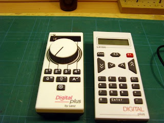
Other work completed on 'Niddbeck Bridge' this week has seen final hooking-up of the'XpressNet' around the layout. This allows you to roam with a handheld throttle and plug-in where ever an outlet facia is located. I have 2 on the rear and one on the front.

Each LA152 facia panel has 3 outlet sockets (2 x DIN type, 1 x phone type). This has allowed me to have both my Lenz handsets working concurrently for the first time. The handset on the left is an LH90 with knob control and LED display and the righthand one is a LH100 with full keypad and LCD display.

Why would I want two handsets you might ask? Both have their good points and bad points and my opinion is that ownership of both is a good idea. The LH100 with its full keypad and better display is great for decoder programming and setting up things generally. On the downside I find the button speed controls not as easy to use as a rotary knob and it only has a loco memory stack of 2 addresses.

The LH90 is an ideal driving and operating throttle but less easy to program with due to the lack of a full keypad. With the large rotary knob and traditional toggle reversing switch I find it easier to drive trains without having to look at the throttle, something I find I often have to do with the LH100. The LH90 also has a loco memory stack of 8 addresses which is much better. When in accessory switching mode, the '2' & '3' buttons allow you to scroll up and down the accessory list adresses (ie points, signals and uncouplers) and the '1' and '4' buttons act as the -/+ switches. Whilst in accessory switching mode the last loco called up remains under full control of the knob and toggle switch, so is an ideal arrangement for shunting.

Another option is to use the LH90 as my loco cab and the LH100 as my signal box. Great fun this DCC business!

Another afterthought has been the addition of a isolated 200mm length of programming track on the fiddle yard, as I thought this might be useful at exhibitions. Prog tracks allow decoder installations to be 'read' and tested at lower power and will avoid a blown decoder if an incorrectly wired or badly insulated loco is subject to full DCC power. It is also safer the change decoder CV settings on an isolated programming track. It can be done 'on the main' but you risk changing settings on other locos if you make a mistake!

Apart from a layout stand and a lighting rig I must now turn my attention to architectural and scenic development of the layout, or proper modelling as no doubt many of you will think!

Edward

Thursday 14 June 2007

Well Stacked...

No, not todays page 3 'stunna' , but my recently constructed DCC power supply and command 'unit'.

I claim no credit for the idea, having copied something similar that Chris Dening (son of Jon Dening, well known ex-Association member, now into 7mm) uses on his Canadian HO exhibition layout.

The idea is to keep all the power supply gubbins, command station and booster (if used) in one floor standing unit and then to feed up to the layout using an 'umbilical cord' on just one plug rather than several. Keeps things neat and tidy, aids storage and transport and speeds up exhibition set-up and break-down times. Or thats the theory anyway!

Construction is quite straightforward; some varnished 9mm birch-faced ply, a length of 1/2" aluminium angle, some 1.5mm ali sheet (cut up from a door finger plate), a couple of 4" aluminium cupboard D-handles and four little rubber feet. Most these items should be obtainable from your local DIY emporium. On the electrical side there are a couple of red indicator lamps and a 25-way D-socket, purchased from Squires.


The two power supply packs (the smaller Lenz TR100 45VA unit which supplies power to the LS150 accessory decoder and the larger Lenz TR150 70VA unit which supplies the LZV100 command station) are the heaviest lumps and these go side by side at the bottom. Above it goes the LZV100 command station (the brains of the DCC system). There is room to add an LV102 booster unit should I ever build a really big layout, or God forbid, move up to the big 7mm+ scales !

The two indicator lamps are wired to the output side of the power packs to give an at-a-glance indication that they are working....beats trying to listen for the gentle hum in a noisy exhibition hall!

Obviously this unit can transfer from layout to layout so should prove to have been time well spent this past week or so.

Edward S

Monday 11 June 2007

After The Ball Was Over

...and after the meeting:


Free Image Hosting at www.ImageShack.us


Nearly there. This work was done Saturday evening and Sunday morning. Polishes up rather nicely, no? The etched handrail have come out better than I expected. Just needs castings affixing, fall-plate attaching and motor inserting.


Free Image Hosting at www.ImageShack.us


Shot of rear of tender. I am not sure about the top lamp bracket. It doesn't seem to match the Isinglass drawings whichever way I affix it. Any suggestions?


Free Image Hosting at www.ImageShack.us


The tender front showing brake and water scoop handles. The instructions indicate that the brackets for these protrude above the ledge. That would seem to make the handles too high and is contrary to photos and drawings I have. I've inverted the bracket and reamed out the holes in the base so that the handles sit lower.


Hopefully this week I'll finish the tender and start the loco proper. I've decided to model a D49/2, but not narrowed it down to a particular loco yet. Watch this space...

Sunday 10 June 2007

Love Me Tender

Some good progress on the D49 over the last few days - pre and post the NEAG meeting.


At the back end of last week I discovered a couple of potential problems.
  1. I'd not read the instructions... No, only joking. However I had missed from the instructions the fact that I ought have fitted the smaller diameter muffs to the tender chassis. This is not covered explicitly in the instructions, but alluded to in the parts list - so if you have a D49 to build, beware. After speaking to Bob and showing him the chassis on Saturday, I'll not take any action just yet. The likely issue is that the front muff will foul the loco-tender connection bush; we will see.
  2. The other concern was that there were no tender axleboxes in the kit and they weren't mentioned in the instructions. Bob told me that they were to be done in whitemetal, but that he had problems with the supplier. Subsequently they have been produced in brass and I received a very nice set on my visit to Bournmoor yesterday. Problem solved!

The photos below show progress before the NEAG meeting:

Free Image Hosting at www.ImageShack.us

The base of the tender body. Rather cunningly, the frames bend down from inside the etched base and the ends bend down from the outside to give a rigid (when soldered) frame. The second layer is then sweated on top of this after the lamp irons and fixing nuts have been appended. The layering must be lined up by eye and a couple of holes to aid this would have been useful.

Free Image Hosting at www.ImageShack.us

Views of the undersides of chassis and base. Note overlarge muffs!


Free Image Hosting at www.ImageShack.us

The body sides have been bent up and soldered to the base - half etched slots are provided to accurately locate the body onto the base. I have also started sweating. I mean started sweating the overlays for the sides/end!

Free Image Hosting at www.ImageShack.us

Another view of the body on the operating table...


After the meeting - see the next post!!


Friday 8 June 2007

A Place Of My Own

One thing I learnt a long time ago was that my modelling was much more enjoyable and my output much greater if I had a dedicated workspace of my own. Trying to model from a portable tool kit on the dining room table was definitely not me!

Here are some images of my new modelling den, located in a large understairs cupboard, purloined from the domestic authorities! The central heating boiler hangs on the wall in the corner so it is all very cosy and snug. Not sure why the builders fitted a radiator as well!

The project has been done on a budget, mainly by negotiating good deals on damaged/soiled stock from a local timber merchant.


This shot shows the understair return which will be my dedicated painting area. The industrial low voltage high intensity lamps with flexible necks are ex-sewing machine lights, obtained 2nd hand and very reasonably priced from Bill Rankin. A plastic desk pen drawer can be seen beneath the worktop.


This shot shows the main workbench along the rear wall, which gives me 2 workstations. 40mm thick kitchen worktop is used for the workbench, the back and sides are lined with adjustable steel shelving uprights with beech effect 'contiboard' infills, tools etc hung on square cup hooks, 6' double fluorescent batten providing general illumination. Several shallow plastic pen drawers fitted under the workbench provide further tool and widget storage. Mains power provided at the back of the bench using hi-fi style mini plugs and 6-way trailing sockets screwed to the back panels (purchased from CPC). These diddy plugs save loads of space and I standardised on them many years ago for my modelling gear.


This shot looking through the door shows shelving above, with 'Niddbeck Bridge' resting on the big shelf. Cheap cardboard postal boxes are used on the upper shelves to store kits and bits.


This shot shows the inside of the door, lined with 'contiboard' and used to store sheet plastic materials in 18"x12" poly bags, hole punched along the top , and hung on rows of 4 square hooks. Packets of wire, Evergreen strip etc also hung on hooks. Old plastic 12" hacksaw blade boxes used for storing metal sections, tubing etc.

Edward S

Thursday 7 June 2007

Fence Houses Insulated Re-Railer Ramp


As promised here is a pic of the DCC-friendly (and DC too) insulated etched re-railer ramp from Fence House Model Foundry.

Plasticard is used to space the two halves apart, and the etched tabs are then snipped out after the epoxy has set. The wedge shaped top guide piece is also plasticard, marked out using the supplied etched template.

The grove that has been filed into the top wheel guide is to clear the iron droppers on DG couplings.
Edward S

Wednesday 6 June 2007

Fresh Impetus

WHERE DOES THE time go? I often ask myself that very question. Usually without reply. Or indeed much modelling taking place.

However last year's AGM certainly provided some much needed inspiration and for the first time in a couple of years I really got back into doing some modelling. I've been mostly concentrating on locomotive construction to build up a stock of decent motive power. I have a couple of completed locomotives which were used extensively on Masham - the J94 on scratchbuilt chassis and the Class 20, again tarted up Farish product - but I want a wider range of locos for any future layout.


I have had a N8 kit tucked away for many years and this has slowly emerged in recent months; you may have read about it on the VAG. This is now in the paintshop and without pausing for breath I have launched myself into a recently acquired D49 kit as commissioned by Edward Sissling and produced by Bob Jones.


Now this is the first time I've built a bespoke 2mm loco kit. The N8 etches are really only a scratchbuilding aid. Whilst I utilised Bob's J27 chassis as the basis of the N8 running gear, there was still much trail and error in the erecting of this loco. I had to devise my own motor mount, fabricated a rear pony truck and work out how the chassis would fit onto and within the loco body.


So I am hoping that building the D49, whilst challenging, will be more straightforward and ultimately a speedier process. Having built some of Bob's rolling stock kits, including some rather nifty little 13T hoppers, I know that his design work is unrivalled in 2mm and probably in 4mm scale too.


To date I have constructed the tender chassis and already I can see the benefits of a completely designed kit; everything has fitted where it ought to with the minimum of reaming and filing needed. Can I maintain the momentum (I've just had a weeks holiday and done no modelling) and make substantial progress? I certainly hope so. I'll keep you all updated...

Here are a couple of views of the tender chassis. The brake rodding is very impressive, but quite straightforward to fabricate. You can just see the "springing" set-up on the inside of the frames as devised by Mick Simpson. The instructions mention this system, but don't explain how to make it! Luckily I've used it before and was familiar with how to fit it in.