Wednesday, 30 January 2008

Saddle up the Palamino

More progress today:

i. Pony Truck. As per instructions. Straightforward, no mistakes (as yet discovered!)


ii. Brakes. Again fairly straightforward; fold up and solder with 0.3mm wires.


iii. Pony Truck on Chassis.


iv. Brakes have been on chassis, but I'm getting binding somewhere. A job for tonight or tomorrow night, perhaps!

Tuesday, 29 January 2008

Under Cover

Are you ever doing some modelling and you get to the point where you think, "Ooh, I never thought about that!"? Well I had just such a revelation at the start of the week.

The D49 chassis is up and running very nicely and all the motion is in place. It's at this stage that I notice the piston rods protruding from the front of the cylinder blocks. "When should they have come off?" I think. "It's going to be a bugger shortening them in situ!" Indeed it is...

I can't find any reference in the instructions as to when I should have shortened them and this makes me feel a little better. Ideally I would have done it before securing the crossheads and slidebars. As it is, I now have to cut them flush with the face of the cylinder without marking the said face too much. Tricky...


The piercing saw proves ideal, but work is slow and careful. Fortunately the piston covers will mask any markings on the cylinder front and the same cover is also half etched where the piston protrudes, so it doesn't have to be dead flush.


Meanwhile the bogie has been assembled and I hope to fit the wheels later tonight or tomorrow. Onward, ever onward...

On a green note, I replaced the bulb in my modelling anglepose lamp with one of these newfangled low energy ones. At 11W it obviously uses lots less electricity, but also the light seems somehow "cleaner" than a 60W standard bulb; I am finding it a lot easier to distinguish fine detail on my work. Additionally the heat thrown off is substantially less; certainly useful once we get into spring/summer.

Saturday, 26 January 2008

... Loco Motion

Motion: Part the Second.

On the right hand side of the D49/2 is the valve-gear; slightly different in that it has Lentz rotary poppet valves. A crank on the foremost driver rotates bevelled gears which drive through a shaft into the cylinder. Further gears and shafts operate the valves in the two cylinders.

Whilst relatively straightforward, the model set-up involves the mock gearbox "floating" on an etched arm and the drive shaft. The bracket, which in real life is attached to the footplate, serves no use in the model and the lining up of the components requires a fair degree of care.

There are no joints to manufacture on this side other than to solder the crank onto the crank-pin capturing the coupling and connecting rods and ensuring that the other end of the crank corresponds to the centre of the wheel. This was done by eye and I think is reasonably successful. If there is any slight misalignment, it is not obvious especially behind the gearbox.


The gearbox is manufactured from a fold up etch onto which we solder a small tube, to take the shaft, and a piece of 0.3mm wire to attach the arm that holds it. This seemed to be going swimmingly until I came to attach the whole to the chassis. On trimming the wires, I loosened the shaft tube; obviously the soldered joint was poor! Reattaching it, now that the gearbox was in-situ and the wires had all been trimmed, proved to be somewhat testing. Eventually I was happy that all was secure and in the correct place. Files and abrasives cleaned up the assembly before the whole chassis was given a thorough wash in the bathroom basin.


I consider the last few days work a success; despite all the gubbins which now adorns the chassis, it still runs very freely - better than I could have hoped for. I have learned some new techniques and pushed back my own modelling boundary a little further. Truth be told, despite the setbacks the motion has actually gone together much less painfully than I thought it would; I guess I can still surprise myself.


Now onto the bogie/pony (?) and then lets get some power to those wheels!

Friday, 25 January 2008

C'mon Baby, Do The...

Little discernable progress with the D49 over the last few weeks as the Layout Challenge kicks off. However I have been redoing the wheels; I was concerned that they were not sufficiently central when looking at the chassis face on. This became more apparent as I proceeded with the loco-motion. So out come the wheels and, similtaneously replacing the muffs, back in they go; hopefully this time more symetrically. This was a tricky process as the slidebars and crossheads are now in place and care is needed not to damage them.

Having undertaken this remedial work, I move onto the motion proper. You may recall that this is the work we are instructed to practice for. And it soon becomes obvious why. The links and arms are miniscule and making moving joints between them is a trial to say the least. This makes soldering coupling rod washers on seem a doddle.

The left hand side is the lubricating motion. At this point the instructions become quite dense and I found myself losing track and failing to understand how the whole was constructed. As well as rereading the instructions several times, I found reference to photographs in the RCTS book most useful and eventually felt confident enough to proceed. Manufacturing the two joints to assemble the three components was fairly straightforward; this work could be completed in the vice and cleaned up with relative ease.


Two close-ups of the motion in various positions. I'm not sure if the swing link should swing quite so much, but it doesn't seem to affect the running...


The assembly must then though be attached to the locomotive and necessitated holding the chassis in a cradle whilst the final joints were made. Attaching the swing link to the bracket on the chassis, the very last joint is the crank onto the the front wheel crank-pin. Being a layer of wheel > coupling rod > connecting rod > washer > crank, extra care was needed to avoid soldering the whole into a horrible mess. Once acheived, the whole lot was carefully cleaned up with files and abrasives and then washed to remove any stray flux.


A quick trundle up the test track reveals a working component; success albeit small in the scheme of things! Now for the other side...

Saturday, 19 January 2008

Lay It All Out

Progress on the Challenge Layout:

i. Here is the basic plan for "Brafferton". The yard lines aren't sketched in yet, but I've incorporated that into the subsequent 3D model. Ultimately the layout will be circular, but to meet the Challenge Rules I've restricted the staging to keep the overall area within 9.42 sqft.

ii. I spent a day or so making a 1/8th scale 3D model to get a better understanding of how the layout might look. The "baseboards" actually represent how the real ones will be constructed.

iii. When modelling, I often do little doodles as below. These aren't necessarily accurate or used in the actual model making. However I use them as inspiration and to get ideas bouncing around.


Tuesday, 15 January 2008

Corporate Blue Diesels..................!

This Class 20 locomotive ran on my very first 2mm Fine Scale layout 'Little Wansbeck' during 1983/4/5.
It has now re emerged on to the scene and as you can see is sporting an etched brass cab.
A lot more realistic than the original Farish jobby.
There isn't much happening to the this particular model at the moment, apart from Bob having etched and fitted a complete cab replacement for it. There are lots of etches available.


It was Edward who asked Bob to do the replacement etches and as he doesn't do diesel Bob asked if I had one of these 'blue boxes' (not his words..!). Well it seemed only right that since Bob was doing the design and he would need a locomotive on which to test out the product that I should volunteer mine....!


So not only do I get a set of test etchings - I don't even have to fit them to my locomotive. The result so far is not perfect, but that has more to do with the original Farish product and my cutting up of it than the etch design, particularly around where the cab roof meets the cab side.


How many more Class 20's out there looking for a face lift? This one is eventually going to end up with a new motor and a decoder.


Mick S

Through the Wires

As promised, here are some pics of the N8 showing the chip installation.

i. General arrangement. The wires have been tweaked a bit more now, so that the front of the chip is higher.


ii. Front view showing the various bits of wiring. There is very little room either side of the motor and none on top where the rear spectacle plate actually touches the top of the motor. In comparison to find space for the wires, getting space for the chip was relatively easy.


iii. As such the wires are visible along the inside of the footplate; being orange doesn't help either! A touch of dark grey should render these much less obtrusive; the light grey one on the other side is less obvious even in its original state.


iv. The chip nestles nicely in the roof space and from all but the lowest viewpoints is invisible. A relative success and fairly quick and easy.


Sunday, 13 January 2008

Lets Get Digital

As I mentioned in the VAG, my Lenz system is now up and running. I have also successfully chipped the N8.

I thought the chip would fit in the tank area, but it soon became apparent that I would need to remove some of the boiler, and associated weight, to get sufficient space above the wheels. The cab area was the backup and I initially decided that I could stick it to the motor with some of the double sticky foam that comes with the chip. This proved to be too obtrusive; the chip and foam were very visible astride the motor.

By then, I'd wired the chip in as per instructions and it became apparent that the wires were sufficiently stiff to carry the chip. I therefore removed the foam and allowed the chip to float free. By tweaking the wires, the chip sits snugly inside the roof area and is substantially less visible. As recommended, I insulated the inside of the body against potential shorts; sellotape worked fine for this.


If I were building the N8 now, I'd allow space to mount the chip in the tanks. The result I have is the best, I think for a loco not built with DCC in mind. Here, with the help of my daughter, are my first tentative steps into DCC;


I'll post some close-ups of the loco in the next day or so.

Friday, 11 January 2008

Still Progressing

Well, Christmas came and went and some progress was made on Niddbeck Bridge, but not as much as I'd hoped. I'm clearly not as disciplined as Tony for the port and single malt somehow always came first!

Most time was expended painting the various structures constructed from dressed stone plasticard. Getting the stone base colour (Humbrol enamel) on was easy enough but then building up on that to give the effect I was looking for was not easy. I wanted that typical industrial north of England dark, sooty, grimy look that was prevalent before the Clean Air Act and 'smokeless' zones came into effect in the 60's. There are not many examples left to see for real. Most buildings and structures have been sandblasted or have had 40-odd years of acid rain and traffic fumes eating the soot away! You can still find examples in sheltered, hidden corners if you look hard enough. I did get there in the end, though I'm not 100% happy with it. I will have to do a better job on the big layout! A topic for the Group to cover during 2008 perhaps?

The platform, bridge and tunnel are now glued in place and a start has been made on the ballasting. This is typical NER/LNER secondary line ash ballast. I experimented with various proprietry dressings and finally settled on a 50/50 mix of Woodland Scenics fine cinders ballast and Busch fine black quartz sand. In due course it will be toned down and blended in by wafting on some highly thinned weathering 'gunge' via airbrush.

In the coming weeks the landform will be added using 'Kingspan' dense insulation foam offcuts scrounged from the skips on the building site on which I live. This will be finished off using an ultra light decorators filler called 'One Strike', a brand we sell at work. Polyfilla do something very similar at twice the price. Once the landform is in place the backscene can be done and I'm still hoping that the Chief Executive of Scorton Village Stores Plc can lend a hand here!

Another job done over the holiday was to put together a test etch of a class 20 diesel cab that Bob has done for me. It went together and looks well but a moment of careless inattention led to irreparable damage to my Farish diecast body. The project is currently stalled pending acquisition of a spare body (and the return of the wheels from Gordon Solloway).

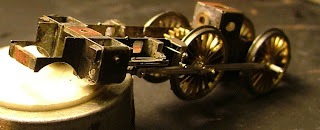
I am finally getting some camera time on the DSLR purchased 4 months ago and Santa bought me a diddy table top tripod for Christmas. Now waiting for delivery of a new and faster card reader then I will start posting pictures on here again.

My new duties as Association Publicity Officer are also mopping up some time. I have quite an exciting project running which will hopefully receive final committee approval soon. All will be revealed via the Magazine in due course!

Friday, 4 January 2008

Golden Jubilee Layout Challenge

Happy New Year!
Now down to business; you have only 30 months to complete your 2mm layout for the said competition. A start now would definitely be a good idea. There are a plethora of blogs springing up detailing progress by various members. Unless I'm expelled for verbal verbosity, I'll tell you about my plans and their execution here on the NEAG blog.
I'll keep my powder relatively dry until I've committed a registration form, but at this time, I can tell you the following:
  1. The layout will be based on a real location.
  2. It is somewhere in the North East of England and set c.1960.
  3. It will utilise almost all of the alloted 9.42 sq ft.
  4. It will be DCC.
  5. Post competition there will be some changes; principally that the staging will be larger and a continuous run established.
  6. I will need to get my finger out post-haste if it is to be anything like!

The Scalefour Society ran a similar challenge a little while ago. If we can emulate the success demonstrated there within our own Association, it would be amazing. There are however, in my opinion, lessons to be learned from our larger brethren:

  1. Make and keep to some sort of timetable, so you aren't building a whole layout two weeks before the show.
  2. Try to work to an overall standard; certain layouts had very poor scenic qualities despite being in "finescale".
  3. Get a bloody backscene. Nobody wants to see a beer belly as a backdrop to a railway!

There we are. I intend to refine my plan over the next week and proceed to cut baseboard material in the middle of January. Meanwhile I need to keep the loco activity moving forward too...!